PRODUCT PROPERTIES

PRODUCT RANGE
TECHNICAL DATA
FIXING SYSTEMS
FIRE CLASSIFICATION
INSTALLATION | MAINTENANCE | STORAGE | HANDLING GUIDELINE

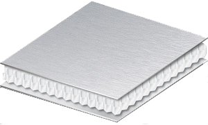
ALUCOBOND®
Download our Alucobond processing manualPROCESSING


ALUCORE® can be cut with a vertical panel saw, circular saw, or a jigsaw.
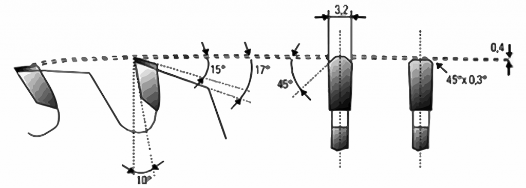
Carbide tipped (CT) saw blades.
Carbide tipped (CT) saw blades for HOLZ-HER and Striebig circular panel saws. Trapezoid/flat tooth saw blade, flat teeth 45° chamfered for burr-free edges. Saw blade-øD = 300 mm (for Striebig vertical panel saw Standard II)
| Blade geometry | Tooth thickness approx. 2 - 4 mm, tapered to the inside to prevent jamming |
| Tooth geometry | Trapezoid tooth / flat tooth |
| Pitch t | 10 - 12 mm |
| Clearance angle α | 15° |
| Rake angle γ | 10° positive |
| Maximum cutting speed v | 5000 m/min |
| Maximum feed s | 30 m/min |
| Number of teeth | t = 72 LEUCO Code No. 18 17 24 |
| Saw blade-ø | D = 250 mm (for Holz-Her vertical panel saw 1255 ALUCORE®) |
| Number of teeth | t = 60 LEUCO Code No. 18 17 26 |
| Bore ø | D = 30 mm |
| Tooth thickness | 3.2 mm |
| Clearance angle α | 15° |
| Rake angle γ | 10 ° positive |
ALUCORE® can be folded on bending presses using the tool geometry shown in the sketch. When measuring cuts, the material gain for the corresponding thickness must be taken into consideration when making 90° folds.
|
Panel thickness (mm) |
Bending radius outside (mm) |
Material gain (mm) |
Folding height min. (mm) |
|---|---|---|---|
| 6 | ~4 | 2.7 | 20 |
| 10 | ~9 | 5.0 | 25 |
| 15 | ~13 | 7.5 | 35 |
| 20 | ~16 | 8.5 | 50 |
| 25 | ~18 | 10.0 | 60 |
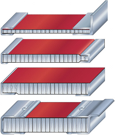
Routing and folding technique / producing corners and edges
Corners and edges can be produced simply on ALUCORE® panels using the routing and folding technique. With all versions, a groove is routed on the rear of the panel into the 1mm thick cover sheet at the front. In version 1, as with ALUCOBOND®, a cutter disk or forming cutter for V-grooves 90° is used in the appropriate width. In version 2, the core of the panel is pre-cut using special tools. The grooves can be produced with circular panel saws and CNC machining centres. Normally, folding by hand is possible. If this is not possible, we recommend the use of a folding machine.Important:
These are customised design tools to match the respective machine and can be ordered by the processor from the recommended manufacturers. Please state the tooth geometry, tool diameter etc. The auxiliary tracing rollers can be produced from the existing ALUCORE® tracing rollers for 4mm or 6 mm thickness.
ALUCORE® can be easily routed on conventional routing machines and CNC machining centres. To avoid pressure marks on the surface, please use plastic or wood vice jaws when working on ALUCORE®. High-speed steel or carbide tipped cutters suitable for aluminium and ALUCORE® have a wide tooth pitch, radiused and smooth grooves and small lip angles. They produce perfect cuts under the following conditions:

- High-speed steel (HSS) max. cutting speed 3,000 m/min max. feed 25 m/min
- Carbide tipped (CT) cutter max. cutting speed 5,000 m/min max. feed 30 m/min
Bending with a roll bending machine
ALUCORE® honeycomb composite panels of 6mm and 10 mm thickness can be bent using three and four-roll bending machines with relatively close radii. The viscoplastic composite system enables radii to be produced from 700mm with a panel thickness of 6mm and from 1,000mm with a panel thickness of 10mm. The minimum diameter of the rolls should be 150mm. The values for adjusting the rolls have to be determined by trial. The bending rolls must be thoroughly cleaned of swarf before processing ALUCORE®. The surface should be protected from damage by affixing plastic strips of 1–2mm thickness during processing.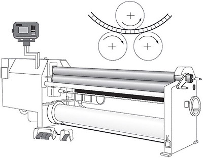
Step-bending with bending presses
ALUCORE® can be shaped using the step-bending process. The bending radius is determined by the stamping depth t, the stamping distance s, and the panel thickness d.
Bending with saw cuts
ALUCORE® can be bent by applying saw cuts on the rear side of the panel. The required radius ra is determined by the tooth thickness s, the wall thickness b, the panel thickness d, and the number of saw cuts. The saw cuts are carried out using the recommended saw blades. To obtain a final thickness of 1.3mm, corresponding tracing rollers are attached to the saw blades of the vertical panel saws. Principally, bending should take place in the 1mm thick cover sheet. Please ask for details.
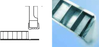
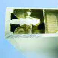
Producing edgings by folding the cover sheets
Routing the panel by means of a special saw blade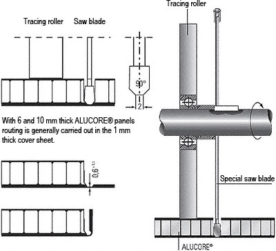 After routing the panel, the honeycomb core and the rear cover sheet are cut off using a joint cutter.
Routing the panel with a cutter disk for rectangular grooves
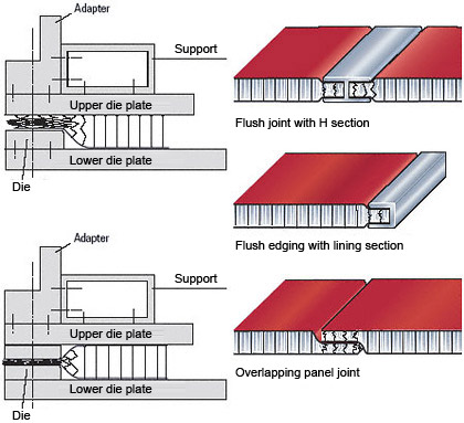
Producing edgings by means of edge bands
Producing edgings using panel edging sections
Producing edgings using panel edging sections
Edges and surfaces of ALUCORE® composite panels can be pressed using bending presses. The core is compressed without destroying the viscoplastic bonding system. This offers new processing and application possibilities.
ALUCORE® can be drilled using twist drills normally used for aluminium and plastics on machines common for metals.

- Drill material: high-speed steel (HSS)
- Tool geometry: lip angle: 100° – 140°
- Drilling without burr is possible using the following drills: Spot facing cutter with centre-point.
- Angle of twist: 30° – 45° e.g. Extreme 2TM HSS-G metal drill DIN 338 of De WALT, Idstein, Germany.
ALUCORE® can be joined by means of standard processes used in metal and plastics technology. If ALUCORE® is to be joined to structural parts of metals other than aluminium, or if fasteners (e.g. bolts, screws) are to be used, the following material guidelines should be observed:
Fasteners and structural parts made of aluminium, plastic or stainless steel should be suitable for assembly with ALUCORE®. When using other materials, please insert insulating washers or apply a protective coating to prevent corrosion.
Please take the thermal expansion of the panel into account for outdoor use of ALUCORE® to avoid jamming or deformation. The minimum gap depends on the expected expansion of the panel. Please refer to processing recommendations for rivets and bolts for additional measures to prevent jamming. The linear thermal expansion of ALUCORE® is determined by the aluminium cover sheets. At a temperature difference of 100°C the longitudinal deformation is 2.4 mm/m length/width.


Rivets – not penetrating the panel
Rivets generally must be anchored in the 1mm thick ALUCORE® cover sheets. Sections can be attached to ALUCORE® with commercially available rivets for aluminium constructions. After drilling a blind hole of the same diameter as the rivet shank, the rivets can be anchored in the cover sheet. As a rule, rivets with stainless steel mandrel are used.
For outdoor use please note:
- For outdoor use aluminium blind rivets that have been approved for construction with a 5 mm shaft diameter and an attachment head diameter of 11 or 14 mm are used.
- Please take the thermal expansion of the panel into account (2.4 mm/m/100°C). To avoid jamming, the hole in the panel must be large enough to allow for expansion.
- With the shaft of the rivet fitting closely to the edge of the hole, the attachment head must cover over 1 mm of the area surrounding the hole.
- Multi-step drills or sleeves having corresponding diameters are used for centrically drilling holes into the panel and the substructure and for centrically fitting the rivet.
- Rivet attachment jigs are used for fitting blind rivets without jamming allowing for a tolerance of 0.3 mm. Make sure to use rivet attachment jigs and rivets from the same manufacturer, as the height of the attachment head according to DIN 7337 may vary.
- The clamping thickness results from the thickness of the material to be riveted plus an additional value of 2 mm to ensure that the closing head is perfectly formed. In accordance with this clamping thickness the corresponding shaft length is determined in the tables provided by the rivet manufacturers.
Important: during riveting many factors may have an influence on the exact tolerance of the rivets of 0.3 mm (e.g. rivet head tolerance), we recommend that you make a test on a fascia panel. Please always remove the protective foil in the riveting area prior to riveting.There are various types of rivet heads and materials which can be selected depending on the intended application. The blind rivet nuts or bolts are inserted in blind holes drilled in one side of the ALUCORE®panel. Subsequent fitting with a tool is fast and cost-effective. (See Fig.) Due to the minimum shaft length of 11 mm these fixtures can only be used for a panel thickness of 15 mm or more. As a rule, the rivet must be anchored in the 1 mm thick cover sheet.
Threaded fasteners for outdoor use
For outdoor use make sure to take the thermal expansion of the panel into account. To avoid jamming, the hole diameter in the panel must allow for the expansion. Fastening without jamming is possible using fascia screws made of stainless steel with sealing washer (Fig. 1) that have been approved for construction. The screws must be suitable for the corresponding substructure (please note the information given by the manufacturer). The screws should be tightened with a torque wrench or screwdriver so that the sealing washer is placed on the panel for sealing the bore hole without exerting pressure to the panel. Multi-step drills or sleeves having corresponding diameters are used for centrically drilling holes into the panel and the substructure and for centrically fitting the rivet. Important: Make sure to remove the protective foil prior to screwing.Examples for threaded fasteners
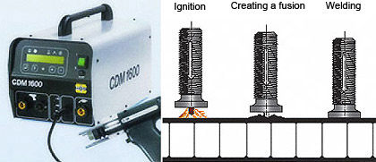
Stud welding with tip ignition on mill-finished ALUCORE® surfaces Process:
- The capacitor battery is charged.
- A spring in the welding gun moves the stud (with tip) towards the work-piece.
- The tip comes into contact with the work-piece and thereby closes the circuit. The rapidly increasing current causes the ignition tip to melt instantaneously, thus initiating the electric arc.
- Stud and work-piece are welded together.
- When the stud touches the work-piece the electric arc is extinguished, the fusion zones on stud and work-piece are joined and solidify.
Tapes/Velcro tapes
Double-sided tapes (such as the 3M-VHB high capacity jointing systems) can be used for the above applications with low tensile or transversal strength requirements. Velcro tapes are available for detachable joints, for example SCOTCHMATE or tapes marketed under the Dual Lock trademark.Adhesive sealing compounds
For high-strength and elastic connections we recommend the following one-component adhesive sealing compound: Sika Bond-T2 (polyurethane base). For outdoor use, this adhesive can be used for fastening parts of minor static importance.Metal adhesives/Universal adhesives
For indoor use, trade fair/exhibition stand structures, machines, etc. most metal or universal a dhesives are suitable.Important:
Please observe the manufacturer’s instructions regarding the application and use of adhesives/tapes. Laminating of ALUCORE® panels to other materials may result in deformation of the laminates (differing expansion/bimetal effect).
Over lacquering of stove lacquered ALUCORE surfaces of polyester lacquer quality (panels not exposed
to weather conditions)
Aluminium treatment and priming carried out at the factory in a continuous process with continuous quality
control is advantageous to the over lacquering of the stove lacquered ALUCORE® surface.
ALUCORE® over lacquering procedure:
- Pre-cleaning of the panels using methylated spirit
- Grinding the surfaces with wet abrasive paper (grain size 360)
- Removing grinding dust with a lint free cloth moistened with spirit
- For the topcoat, please follow the instructions of the topcoat supplier.
Please note:
- The maximum permissible temperature of the material (ALUCORE® panels) must not exceed 70°C when applying fast-drying methods. During the drying process at high temperatures the ALUCORE® panels must be positioned or stored with great care to prevent deforming.
- ALUCORE® cut edges should not be in contact with organic solvents for a prolonged period of time to avoid weakening the bond.
- ALUCORE® panels lacquered or over lacquered at a later stage should not be bent or folded. The lacquer in the bends or folds may be damaged due to the low elasticity of the topcoat.